Import
| |||||||||||||||||||||||||||||||||||||||||||||||||||||||||||||||||||||||||||||||||||||||||||||||||||||||||||||||||||||||||||||||||||||||||||||||||||||||||||||||||||||||||||||||||||||||||||||||||||||||||||||||||||||||||||||||||||||||||||||||||||||||||||||||||||||||||||||||||||||||||||||||||||||||||||||||||||||||||||||||||||||||||||||||||||||||||||||||||||||||||||||||||||||||||||||||||||||||||||||||||||||||||||||||||||||||||||||||||||||||||||||||||||||||||||||||||||||||||||||||||||||||||||||||||||||||||||||||||||||||||||||||||||||||||||||||||||||||||||||||||||||||||||||||||||||||||||||||||||||||||||||||||||||||||||||||||||||||||||||||||||||||||||||||||||||||||||||||||||||||||||||||||||||||||||||||||||||||||||||||||||||||||||||||||||||||||||||||||||||||||||||||||||||||||||||||||||||||||||||||||||||||||||||||||||||||||||||||||||||||||||||||||||||||||||||||||||||||||||||||||||||||||||||||||||||||||||||||||||||||||||||||||||||||||||||||||||||||||||||||||||||||||||||||||||||||||||||||||||||||
|
Import MGT files as well as other types of files. | |||||||||||||||||||||||||||||||||||||||||||||||||||||||||||||||||||||||||||||||||||||||||||||||||||||||||||||||||||||||||||||||||||||||||||||||||||||||||||||||||||||||||||||||||||||||||||||||||||||||||||||||||||||||||||||||||||||||||||||||||||||||||||||||||||||||||||||||||||||||||||||||||||||||||||||||||||||||||||||||||||||||||||||||||||||||||||||||||||||||||||||||||||||||||||||||||||||||||||||||||||||||||||||||||||||||||||||||||||||||||||||||||||||||||||||||||||||||||||||||||||||||||||||||||||||||||||||||||||||||||||||||||||||||||||||||||||||||||||||||||||||||||||||||||||||||||||||||||||||||||||||||||||||||||||||||||||||||||||||||||||||||||||||||||||||||||||||||||||||||||||||||||||||||||||||||||||||||||||||||||||||||||||||||||||||||||||||||||||||||||||||||||||||||||||||||||||||||||||||||||||||||||||||||||||||||||||||||||||||||||||||||||||||||||||||||||||||||||||||||||||||||||||||||||||||||||||||||||||||||||||||||||||||||||||||||||||||||||||||||||||||||||||||||||||||||||||||||||||||||
|
| |||||||||||||||||||||||||||||||||||||||||||||||||||||||||||||||||||||||||||||||||||||||||||||||||||||||||||||||||||||||||||||||||||||||||||||||||||||||||||||||||||||||||||||||||||||||||||||||||||||||||||||||||||||||||||||||||||||||||||||||||||||||||||||||||||||||||||||||||||||||||||||||||||||||||||||||||||||||||||||||||||||||||||||||||||||||||||||||||||||||||||||||||||||||||||||||||||||||||||||||||||||||||||||||||||||||||||||||||||||||||||||||||||||||||||||||||||||||||||||||||||||||||||||||||||||||||||||||||||||||||||||||||||||||||||||||||||||||||||||||||||||||||||||||||||||||||||||||||||||||||||||||||||||||||||||||||||||||||||||||||||||||||||||||||||||||||||||||||||||||||||||||||||||||||||||||||||||||||||||||||||||||||||||||||||||||||||||||||||||||||||||||||||||||||||||||||||||||||||||||||||||||||||||||||||||||||||||||||||||||||||||||||||||||||||||||||||||||||||||||||||||||||||||||||||||||||||||||||||||||||||||||||||||||||||||||||||||||||||||||||||||||||||||||||||||||||||||||||||||||
|
From the Main Menu select File > Import > MIDAS/Gen MGT File.
From the Main Menu select File > Import > AutoCAD DXF File.
From the Main Menu select File > Import > SAP2000(V6, V7) File.
From the Main Menu select File > Import > SAP2000(V8) File.
From the Main Menu select File > Import > STAAD2000 File.
From the Main Menu select File > Import > STAAD2002 File. | |||||||||||||||||||||||||||||||||||||||||||||||||||||||||||||||||||||||||||||||||||||||||||||||||||||||||||||||||||||||||||||||||||||||||||||||||||||||||||||||||||||||||||||||||||||||||||||||||||||||||||||||||||||||||||||||||||||||||||||||||||||||||||||||||||||||||||||||||||||||||||||||||||||||||||||||||||||||||||||||||||||||||||||||||||||||||||||||||||||||||||||||||||||||||||||||||||||||||||||||||||||||||||||||||||||||||||||||||||||||||||||||||||||||||||||||||||||||||||||||||||||||||||||||||||||||||||||||||||||||||||||||||||||||||||||||||||||||||||||||||||||||||||||||||||||||||||||||||||||||||||||||||||||||||||||||||||||||||||||||||||||||||||||||||||||||||||||||||||||||||||||||||||||||||||||||||||||||||||||||||||||||||||||||||||||||||||||||||||||||||||||||||||||||||||||||||||||||||||||||||||||||||||||||||||||||||||||||||||||||||||||||||||||||||||||||||||||||||||||||||||||||||||||||||||||||||||||||||||||||||||||||||||||||||||||||||||||||||||||||||||||||||||||||||||||||||||||||||||||||
|
| |||||||||||||||||||||||||||||||||||||||||||||||||||||||||||||||||||||||||||||||||||||||||||||||||||||||||||||||||||||||||||||||||||||||||||||||||||||||||||||||||||||||||||||||||||||||||||||||||||||||||||||||||||||||||||||||||||||||||||||||||||||||||||||||||||||||||||||||||||||||||||||||||||||||||||||||||||||||||||||||||||||||||||||||||||||||||||||||||||||||||||||||||||||||||||||||||||||||||||||||||||||||||||||||||||||||||||||||||||||||||||||||||||||||||||||||||||||||||||||||||||||||||||||||||||||||||||||||||||||||||||||||||||||||||||||||||||||||||||||||||||||||||||||||||||||||||||||||||||||||||||||||||||||||||||||||||||||||||||||||||||||||||||||||||||||||||||||||||||||||||||||||||||||||||||||||||||||||||||||||||||||||||||||||||||||||||||||||||||||||||||||||||||||||||||||||||||||||||||||||||||||||||||||||||||||||||||||||||||||||||||||||||||||||||||||||||||||||||||||||||||||||||||||||||||||||||||||||||||||||||||||||||||||||||||||||||||||||||||||||||||||||||||||||||||||||||||||||||||||||
|
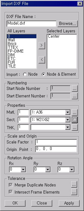
Import DXF File dialog box
Note 1
Even in case of element shape errors (e.g., overlapping nodes) during DXF file import, the import can be executed as the program is ignoring the parts with errors. In the message window, the following error messages will display. "[WARNING] Invalid Node(No.XX) is skipped!", "[WARNING] Invalid Element(No.XX) is skipped!"
Polyline cannot be imported. Split a Polyline into Lines.
Note 2 Various polyline types, such as polygon, triangle, rectangle, etc., can be imported to midas Gen as plate elements in .DXF format, where plate elements are imported as thick type (without drilling DOF)
| |||||||||||||||||||||||||||||||||||||||||||||||||||||||||||||||||||||||||||||||||||||||||||||||||||||||||||||||||||||||||||||||||||||||||||||||||||||||||||||||||||||||||||||||||||||||||||||||||||||||||||||||||||||||||||||||||||||||||||||||||||||||||||||||||||||||||||||||||||||||||||||||||||||||||||||||||||||||||||||||||||||||||||||||||||||||||||||||||||||||||||||||||||||||||||||||||||||||||||||||||||||||||||||||||||||||||||||||||||||||||||||||||||||||||||||||||||||||||||||||||||||||||||||||||||||||||||||||||||||||||||||||||||||||||||||||||||||||||||||||||||||||||||||||||||||||||||||||||||||||||||||||||||||||||||||||||||||||||||||||||||||||||||||||||||||||||||||||||||||||||||||||||||||||||||||||||||||||||||||||||||||||||||||||||||||||||||||||||||||||||||||||||||||||||||||||||||||||||||||||||||||||||||||||||||||||||||||||||||||||||||||||||||||||||||||||||||||||||||||||||||||||||||||||||||||||||||||||||||||||||||||||||||||||||||||||||||||||||||||||||||||||||||||||||||||||||||||||||||||||

|
SAP2000 command |
Detail command |
Conversion |
Limitation |
MIDAS/Gen function |
|
System |
DOF |
O |
- |
|
|
LENGTH, FORCE |
O |
- |
*UNIT | |
|
CYC |
O |
Converted into Static Analysis in the case of Harmonic Steady-State Analysis |
- | |
|
COORDINATE |
- |
O |
- |
- |
|
JOINT |
- |
O |
- |
*NODE |
|
LOCAL |
ANG |
O |
- |
|
|
AXVEC, PLVEC |
O |
- |
||
|
RESTRAINT |
- |
O |
- |
|
|
CONSTRAINT (1) |
- |
O |
- |
|
|
WELD |
- |
X |
- |
- |
|
PATTERN |
- |
O |
- |
- |
|
SPRING |
- |
O |
- |
- |
|
MASS |
- |
O |
- |
- |
|
MATERIAL (2) |
Isotropic |
O |
- |
|
|
Orthotropic |
O |
Only one axis converted |
||
|
Anisotropic |
O |
Only one axis converted |
||
|
FRAME SECTION (3) |
Prismatic R, P, B, C, T, A, I, L, 2L Shape Section |
O |
- |
|
|
Prismatic General Section |
O |
- |
||
|
Prismatic Database Section |
X |
- |
- | |
|
Nonprismatic Section |
O |
- |
||
|
SHELL SECTION |
- |
O |
- |
|
|
NLPROP (4) |
- |
O |
- |
|
|
FRAME |
GEN, DEL |
O |
- |
|
|
LOCAL, ANG, PLVEC |
O |
- |
||
|
IOFF, JOFF |
O |
- |
||
|
RIGID (5) |
O |
Converted into 1.0 for a value other than 1.0. |
||
|
IREL, JREL |
O |
- |
||
|
SHELL |
GEN, DEL |
O |
- |
|
|
PLVEC,ANG |
X |
- |
- | |
|
PLANE |
GEN, DEL |
O |
- |
|
|
3,4 Node element |
O |
- |
||
|
9 Node element |
X |
- |
- | |
|
MATANG |
X |
- |
- | |
|
ASOLID |
GEN, DEL |
O |
- |
|
|
3,4 Node element |
O |
- |
||
|
9 Node element |
X |
- |
- | |
|
MATANG, ARC |
X |
- |
- | |
|
SOLID |
GEN, DEL |
O |
- |
|
|
6,8 Node element |
O |
- |
||
|
MATANG |
X |
- |
- | |
|
NLLINK (6) |
1 Node element |
O |
- |
|
|
2 Node element |
O |
- |
||
|
MATTEMP |
- |
X |
- |
- |
|
REFTEMP |
- |
O |
- |
- |
|
PRESTRESS |
- |
O |
- |
|
|
LOAD |
FORCE |
O |
- |
|
|
RESTRAINT |
O |
- |
||
|
SPRING |
O |
MIDAS does not have a corresponding command. Converted into Specified Displacement at the closest support. |
||
|
GRAVITY (Beam) |
O |
- |
||
|
GRAVITY (Shell) |
O |
- |
||
|
GRAVITY (Plane/Asolid/Solid) |
X |
- |
- | |
|
CONCENTRATED SPAN |
O |
- |
||
|
DISTRIBUTED SPAN |
O |
- |
||
|
PRESTRESS |
O |
- |
||
|
UNIFORM |
O |
- |
||
|
SURFACE PRESSURE |
O |
- |
||
|
PORE PRESSURE |
X |
- |
- | |
|
TEMPERATURE |
O |
- |
||
|
ROTATE |
X |
- |
- | |
|
PDFORCE |
- |
O |
- |
|
|
PDELTA |
- |
O |
- |
|
|
MODES |
N,CUT,TOL |
O |
- |
|
|
RITZ |
O |
- |
||
|
SHIFT |
X |
- |
- | |
|
ACC, LOAD, NCYC, NLLINK |
X |
- |
- | |
|
FUNCTION |
The file being used by FUNCTION must be in the same folder containging *.s2k. |
O |
If a file is used for FUNCTION, the file must be in the same folder, which contains *.2k. |
|
|
SPEC |
NAME, ANG, DAMP, F1, F2, DIRF,MODC (CQC,SRSS,ABS) |
O |
- |
|
|
MODC (GMC) |
X |
- |
- | |
|
HISTORY |
Linear Transient/ |
O |
- |
|
|
Nonlinear Transient Analysis |
X |
- |
- | |
|
Acceleration Data |
O |
- |
||
|
Load Data (7) |
O |
- |
||
|
LANE |
- |
O |
- |
|
|
VEHICLE |
DB Vehicle (8) |
O |
- |
|
|
User Define Vehicle |
X |
Converted into DB24 vehicle load & a warning issued. |
||
|
VEHICLE CLASS |
- |
O |
- |
|
|
BRIDGE RESPONSE |
- |
X |
- |
- |
|
MOVING LOAD |
NAME, RF, CLASS, LANE, LMIN, LMAX, SF |
O |
- |
|
|
CALC |
O |
- |
||
|
TOL, SET |
X |
- |
- | |
|
COMBO |
- |
O |
- |
|
|
Output |
- |
X |
- |
|
|
END |
- |
X |
- |
|
Notes
1. CONSTRAINT
¨ Constraint of DIAPH, PLATE, ROD or BEAM Type having Auto Axis is converted into Global Z Axis.
¨ The node closest to the center of the constrained nodes defined in SAP2000 is converted into the Master Node in MIDAS.
¨ EQUAL and LOCAL are converted into the Rigid Link of MIDAS, and a warning message is generated.
2. MATERIAL
¨ SAP2000 uses Weight Density and Mass Density. If Mass Density exists in the absence of Weight Density, the Mass Density is converted into Weight Density (Weight Density = Mass Density * Gravitational acceleration).
¨ When Mass Density exists, the form of Converting Type of Model Weights to Masses of Structure Type in MIDAS is transformed into Convert to X,Y,Z.
3. FRAME SECTION
¨ MPL (Mass Per Length) assigned to Frame Element is converted into Nodal Mass at each end of the element.
¨ WPL (Weight Per Length) assigned to Frame Element is converted into Beam Load. The Beam Load is included in the load case containing Gravity Load.
4. NLPROP
¨ Elements pertaining to NLLINK are converted into Elastic Link in MIDAS. Only the linear stiffness of NLPROP is retained.
¨ If both KE and K exist, KE is converted into the stiffness of Elastic Link.
¨ If K alone exists in the absence of KE, K is converted into the stiffness of Elastic Link.
¨ If neither KE nor K exists, 0 is assigned to the stiffness of Elastic Link.
5. RIGID
¨ RIGID in SAP2000 represents the Factor of Rigidity in the Offset part defined in Frame. 1 and 0 signify Fully Rigid and Fully Flexible respectively. MIDAS permits only the Fully Rigid case.
6. NLLINK
¨ 1-node NLLINK is converted into Spring support and 2-node NLLINK is converted into Elastic link.
7. Load Data
¨ Dynamic Nodal Load in MIDAS is defined by applying loads at specific nodes, whereas Static Load Case is assigned in SAP2000 for such loads. If nodal loads exist in Static Load Case, Load Function is assigned to the corresponding nodes. If no such nodal loads exist in Static Load Case, no conversion is carried out and a warning message is generated.
8. Vehicle loads
¨ Convertible Vehicle loads: COOPERE80, P5, P7, P9, P11, P13, AML
¨ Vehicle loads not converted: HL-93M, HL-93K, HL-93S, RL, HN-44, HSN-44, HN-44L, HSN-44L
¨ Converted into DB24 Load and a warning message is generated.
 SAP2000(V8)
File
SAP2000(V8)
File
**Target File: Unmodified *.s2k file created by Export in SAP2000(V8) can be converted.
|
Contents |
Table |
Conversion |
MIDAS |
Remarks |
|
Joint |
Summary - Joint Assignments |
O |
- |
|
|
Joint Coordinates |
O |
*NODE |
| |
|
Joint Restraint Assignments |
O |
| ||
|
Joint Local Axes Assignments 1 - Typical |
O |
| ||
|
Joint Local Axes Assignments 2 - Advanced |
O |
| ||
|
Joint Pattern Assignments(1) |
O |
- |
| |
|
Joint Pattern Definitions(1) |
O |
- |
| |
|
Joint Spring Assignments 1 - Uncoupled |
O |
| ||
|
Joint Spring Assignments 2 - Coupled |
O |
| ||
|
Joint Panel Zone Assignments |
X |
- N/A |
| |
|
Frame |
Summary - Frame Assignments |
O |
|
|
|
Connectivity - Frame/Cable |
O |
| ||
|
Frame Cable Assignments |
X |
|
| |
|
Frame Design Procedures |
X |
|
| |
|
Frame Insertion Point Assignments |
O |
| ||
|
Frame Local Axes Assignments 1 - Typical |
O |
| ||
|
Frame Local Axes Assignments 2 - Advanced |
O |
| ||
|
Frame Material Temperatures |
X |
- N/A |
| |
|
Frame NL Hinge Assignments |
X |
|
| |
|
Frame Offset Along Length Assignments(2) |
O |
| ||
|
Frame Output Station Assignments |
X |
- N/A |
| |
|
Frame P-Delta Force Assignments |
O |
| ||
|
Frame Prestress 1 - Patterns |
O |
| ||
|
Frame Prestress 2 - Load Multipliers |
O |
| ||
|
Frame Property Modifiers |
O |
| ||
|
Frame Reference Temperatures |
O |
| ||
|
Frame Release Assignments 1 - General(3) |
O |
| ||
|
Frame Release Assignments 2 - Partial Fixity(3) |
|
| ||
|
Frame Spring Assignments(4) |
|
| ||
|
Frame Auto Subdivision Assignments |
X |
- N/A |
| |
|
Frame Tension And Compression Limits |
X |
- |
| |
|
Area |
Summary - Area Assignments |
O |
|
|
|
Connectivity - Area(5) |
O |
| ||
|
Area Auto Mesh Assignments |
X |
- N/A |
| |
|
Area Local Axes Assignments 1 - Typical(6) |
X |
- Undefined |
| |
|
Area Local Axes Assignments 2 - Advanced(6) |
X |
- Undefined |
| |
|
Area Material Temperatures |
X |
- N/A |
| |
|
Area Reference Temperatures |
O |
| ||
|
Area Spring Assignments(5) |
|
| ||
|
Solid |
Summary - Solid Assignments |
O |
- |
|
|
Connectivity - Solid |
O |
| ||
|
Solid Local Axes Assignments 1 - Typical(6) |
X |
- Undefined |
| |
|
Solid Local Axes Assignments 2 - Advanced(6) |
X |
- Undefined |
| |
|
Solid Material Temperatures |
X |
- N/A |
| |
|
Solid Property Assignments |
X |
- N/A |
| |
|
Solid Property Definitions |
X |
- N/A |
| |
|
Solid Reference Temperatures |
O |
| ||
|
Solid Spring Assignments(4) |
X |
- Undefined |
| |
|
Solid Auto Mesh Assignments |
X |
- N/A |
| |
|
Link |
Summary - Link Assignments |
O |
- |
|
|
Connectivity - Link |
O |
| ||
|
Link Local Axes Assignments 1 - Typical |
O |
| ||
|
Link Local Axes Assignments 2 - Advanced |
O |
| ||
|
Link Property Definitions 01 - General |
O |
| ||
|
Link Property Definitions 02 - Linear |
O |
| ||
|
Link Property Definitions 03 - MultiLinear |
X |
- N/A |
| |
|
Link Property Definitions 04 - Damper |
O |
| ||
|
Link Property Definitions 05 - Gap |
O |
| ||
|
Link Property Definitions 06 - Hook |
O |
| ||
|
Link Property Definitions 07 - Rubber Isolator |
O |
| ||
|
Link Property Definitions 08 - Sliding Isolator |
O |
| ||
|
Link Property Definitions 09 - Plastic (Wen) |
O |
| ||
|
Link Property Definitions 10 - Plastic (Kinematic) |
X |
- N/A |
| |
|
Link Property Assignments |
O |
| ||
|
|
Program Control |
O |
*UNIT |
|
|
MATERIAL |
Material Properties 1 - General |
O |
| |
|
Material Properties 2 - Advanced |
|
- anisotropic | ||
|
Material Properties 3 - Design Steel |
X |
- |
| |
|
Material Properties 4 - Design Concrete |
X |
- |
| |
|
Material Properties 5 - Design Aluminum |
X |
|
| |
|
Material Properties 6 - Design ColdFormed |
X |
|
| |
|
SECTION |
Frame Section Assignments |
O |
| |
|
Frame Section Properties 1 - General |
O |
| ||
|
Frame Section Properties 2 - Concrete Column |
X |
|
| |
|
Frame Section Properties 3 - Concrete Beam |
X |
|
| |
|
Frame Section Properties 4 - Auto Select |
X |
|
| |
|
Frame Section Properties 5 - Nonprismatic |
|
- sect. scale | ||
|
Thickness |
Area Section Properties |
O |
| |
|
Area Stiffness Modifiers |
O |
- N/A |
| |
|
Static Load Case |
Joint Loads - Force |
O |
| |
|
Joint Loads - Ground Displacement |
O |
| ||
|
Frame Loads - Distributed |
O |
| ||
|
Frame Loads - Gravity(7) |
O |
- SelfModifier | ||
|
Frame Loads - Point |
O |
| ||
|
Frame Loads - Temperature(8) |
O |
- Joint Pattern | ||
|
Area Loads - Gravity(7) |
O |
- SelfModifier | ||
|
Area Loads - Pore Pressure |
X |
- N/A |
| |
|
Area Loads - Rotate |
X |
- N/A |
| |
|
Area Loads - Surface Pressure |
O |
| ||
|
Area Loads - Temperature(8) |
O |
| ||
|
Area Loads - Uniform To Frame |
X |
- Lack of data |
- FLOADTYPE | |
|
Area Loads - Uniform |
O |
- Joint Pattern | ||
|
Area Loads - Wind Pressure Coefficients |
X |
- Undefined |
| |
|
Solid Loads - Gravity(7) |
X |
- Undefined |
- SelfModifier | |
|
Solid Loads - Pore Pressure |
X |
- N/A |
| |
|
Solid Loads - Surface Pressure |
X |
- Undefined |
| |
|
Solid Loads - Temperature(8) |
O |
| ||
|
Link Loads - Gravity(7) |
X |
- N/A |
| |
|
Case - Static 1 - Load Assignments |
O |
| ||
|
Load Case Definitions |
O |
| ||
|
LOAD |
Bridge Loads 1 - Lane Definitions |
O |
- Both | |
|
Bridge Loads 2 - Standard Vehicles |
O |
| ||
|
Bridge Loads 3 - General Vehicles 1 |
O |
| ||
|
Bridge Loads 4 - General Vehicles 2 |
O |
| ||
|
Bridge Loads 5 - Vehicle Classes |
O |
| ||
|
Bridge Loads 6 - Bridge Response |
O |
| ||
|
Case - Moving Load 1 - Lane Assignments |
O |
| ||
|
Case - Moving Load 2 - Lanes Loaded |
O |
| ||
|
Case - Moving Load 3 - MultiLane Factors |
O |
*MVLDCASE- |
| |
|
|
Combination Definitions |
O |
| |
|
Eigen Value Problem |
Masses 1 - Mass Source |
O |
| |
|
Masses 2 - Assembled Joint Masses |
X |
- Generated after analysis |
| |
|
Joint Added Mass Assignments |
O |
| ||
|
Frame Added Mass Assignments(9) |
|
| ||
|
Area Added Mass Assignments(9) |
|
| ||
|
Case - Modal 1 - General |
O |
| ||
|
Case - Modal 2 - Load Assignments - Eigen |
X |
- N/A |
| |
|
Case - Modal 3 - Load Assignments - Ritz |
O |
| ||
|
Response Spectrum Analysis |
Function - Response Spectrum - BOCA96 |
X |
- N/A |
|
|
Function - Response Spectrum - EuroCode8 |
O |
| ||
|
Function - Response Spectrum - From File |
X |
- N/A |
| |
|
Function - Response Spectrum - IBC2000 |
O |
| ||
|
Function - Response Spectrum - NBCC95 |
O |
| ||
|
Function - Response Spectrum - NEHRP97 |
X |
- N/A |
| |
|
Function - Response Spectrum - NZS4203 |
X |
- N/A |
| |
|
Function - Response Spectrum - UBC94 |
O |
| ||
|
Function - Response Spectrum - UBC97 |
O |
| ||
|
Function - Response Spectrum - User |
O |
| ||
|
Case - Response spectrum 1 - General(10) |
O |
*SPEC-CTRL |
| |
|
Case - Response spectrum 2 - Load Assignments(10) |
O |
| ||
|
Case - Response spectrum 3 - Interpolated Damping |
X |
- N/A |
| |
|
Case - Response spectrum 4 - Proportional Damping |
X |
- N/A |
| |
|
Case - Response spectrum 5 - Damping Overrides |
X |
- N/A |
| |
|
Analysis |
Analysis Case Definitions |
O |
| |
|
Active Degrees of Freedom |
O |
| ||
|
Case - Static 2 - Nonlinear Load Application |
X |
|
| |
|
Case - Static 3 - Nonlinear Stage Information |
X |
- Lack of data |
*STAGE | |
|
Case - Static 4 - Nonlinear Parameters |
X |
- Lack of data |
*STAGE | |
|
Case - Direct History 1 - General(11) |
O |
| ||
|
Case - Direct History 2 - Load Assignments |
O |
| ||
|
Case - Direct History 3 - Proportional Damping |
O |
| ||
|
Case - Direct History 4 - Integration Parameters |
X |
- N/A |
| |
|
Case - Direct History 5 - Nonlinear Parameters |
O |
| ||
|
Case - Modal History 1 - General |
O |
| ||
|
Case - Modal History 2 - Load Assignments |
O |
| ||
|
Case - Modal History 3 - Interpolated Damping |
X |
- N/A |
| |
|
Case - Modal History 4 - Proportional Damping |
O |
| ||
|
Case - Modal History 5 - Damping Overrides |
O |
| ||
|
Case - Modal History 6 - Nonlinear Parameters |
O |
| ||
|
Case - Buckling 1 - General(12) |
O |
| ||
|
Case - Buckling 2 - Load Assignments |
O |
| ||
|
Case - Steady State 1 - General |
X |
|
| |
|
Case - Steady State 2 - Load Assignments |
X |
|
| |
|
Rigid Link |
Joint Constraint Assignments(13) |
O |
| |
|
Constraint Definitions - Beam |
|
- Auto Axes | ||
|
Constraint Definitions - Body |
O |
| ||
|
Constraint Definitions - Diaphragm |
|
- Auto Axes | ||
|
Constraint Definitions - Equal |
O |
| ||
|
Constraint Definitions - Line |
O |
| ||
|
Constraint Definitions - Local |
X |
- N/A |
| |
|
Constraint Definitions - Plate |
|
- Auto Axes | ||
|
Constraint Definitions - Rod |
|
- Auto Axes | ||
|
Constraint Definitions - Weld |
O |
| ||
|
Lateral Load (Wind) |
Auto Wind - ASCE7-88 |
X |
- N/A |
|
|
Auto Wind - ASCE7-95 |
X |
- N/A |
| |
|
Auto Wind - ASCE7-98 |
O |
*WIND |
| |
|
Auto Wind - BOCA96 |
X |
- N/A |
| |
|
Auto Wind - BS6399-95 |
X |
- Lack of data |
| |
|
Auto Wind - NBCC95 |
O |
*WIND |
| |
|
Auto Wind - UBC94 |
X |
- N/A |
| |
|
Auto Wind - UBC97 |
O |
*WIND |
| |
|
Auto Wind - User |
X |
- N/A |
| |
|
Auto Wind Exposure For Horizontal Diaphragms |
X |
- N/A |
| |
|
Auto Wind Loads To Groups |
X |
- N/A |
| |
|
Auto Wind Loads To Horizontal Diaphragms |
X |
- N/A |
| |
|
Auto Wind Loads To Joints |
X |
- N/A |
| |
|
Lateral Load (Seismic) |
Auto Seismic - BOCA96 |
X |
- N/A |
|
|
Auto Seismic - IBC2000 |
X |
- Lack of data |
- Seismic Group | |
|
Auto Seismic - NBCC95 |
O |
*SEIS |
| |
|
Auto Seismic - NEHRP97 |
X |
- N/A |
| |
|
Auto Seismic - UBC94 |
X |
- N/A |
| |
|
Auto Seismic - UBC97 |
O |
*SEIS |
| |
|
Auto Seismic - UBC97 Isolated |
X |
- N/A |
| |
|
Auto Seismic - User Coefficient |
X |
- N/A |
| |
|
Auto Seismic - User Loads |
X |
- N/A |
| |
|
Auto Seismic Eccentricity Overrides |
X |
- N/A |
| |
|
Auto Seismic Loads To Groups |
X |
- N/A |
| |
|
Auto Seismic Loads To Horizontal Diaphragms |
X |
- N/A |
| |
|
Auto Seismic Loads To Joints |
X |
- N/A |
| |
|
Time History Functions |
Function - Time History - Cosine |
X |
- N/A |
|
|
Function - Time History - From File |
O |
| ||
|
Function - Time History - Ramp |
X |
- N/A |
| |
|
Function - Time History - Sawtooth |
X |
- N/A |
| |
|
Function - Time History - Sine |
X |
- N/A |
| |
|
Function - Time History - Triangular |
X |
- N/A |
| |
|
Function - Time History - User |
O |
| ||
|
Function - Time History - User Periodic |
X |
- N/A |
| |
|
COMBO |
Groups 1 - Definitions |
X |
|
|
|
Output |
Groups 2 - Assignments |
X |
- Lack of data |
*GROUP |
|
END |
Groups 3 - Masses and Weights |
X |
|
|

Notes
Commentary
1. Joint Pattern
¨ For the present, it is applied to Element Temperature Load, Temperature Gradient and Area Surface Load.
2. Beam End Offset
¨ No Rigid Factor function
Note
Converted into Fully Rigid Offset
3. Beam End Release
¨ SAP inputs Partial Fixity as Stiffness whereas MIDAS inputs it as Proportion in the case of Frame Release.
Note
Converted into Full Fixity
4. Element Spring
¨ Frame Spring Assignment: Converted into Node Spring
¨ Area Spring Assignment: Converted into Node Spring (only in the case of face#5 and #6 (∵local axes))
¨ Solid Spring Assignment: Not converted since local axes are not defined
5. Area element
|
SAP2000(V8) |
MIDAS/Gen |
Remark | |||
|
Section-Type |
sub-type |
Element |
type | ||
|
Shell |
Shell |
Thick |
Plate(5-1) |
Thick |
|
|
Thin |
Thin |
| |||
|
Membrane |
Plane Stress(5-2) |
| |||
|
Plate |
Thick |
Plate |
Thick |
Consistent Element Properties | |
|
Thin |
Thin | ||||
|
Plane |
Stress |
Plane |
Stress |
Consistent Element Properties | |
|
Strain |
Strain | ||||
|
Asolid |
Axisymmetric solid |
Consistent Element Properties | |||
5-1. In SAP 2000, Shell-Shell Element is the combination of Shell-Membrane Element and Shell-Plate Element, and the element has both translational and rotational degrees of freedom in ECS (element coordinate system) x, y, and z directions. In MIDAS/Gen, however, since there is no corresponding element to Shell-Shell Element of SAP 2000, it is converted into Plate Element.
5-2. In SAP 2000, Shell-Membrane Element has translational degrees of freedom in two in-plane directions and a rotational degree of freedom (drilling moment) perpendicular to the plane. As the counterpart of MIDAS/Gen, Wall-Membrane Element may be used. But it has a limitation in that the nodes of Wall-Membrane Element have to be connected counterclockwise starting from the bottom left and the element must be parallel to the Global Z-axis. Due to the limitations, the Shell-Membrane Element of SAP2000 is replaced with the Plane-Stress Element of MIDAS, which has only translational degrees of freedom in two in-plane directions.
6. Local Axes
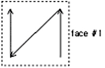
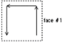
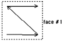
¨ Area Local Axes: SAP - default: Identical to GLOBAL Axes
MIDAS - default: Local Axes are defined by the sequence of nodes.
|
|
SAP2000 (default:GLOBAL) |
MIDAS/Gen |
|---|---|---|
|
Ex(1) |
|
|
|
Ex(2) |
|
|
7. Gravity Load
¨ Frame: Converted into Element Beam Load (*if self modifier > 0, self weight is applied)
¨ Area: Converted into Pressure Load (in the direction of Global Axes of face#5, #6 since local axes are not defined)
¨ Solid: Not converted since local axes are not defined
8. Temperature Load
¨ Frame Temperature Load
¨ It is converted into Nodal Temperature if Joint Pattern exists. The average of Joint Pattern is converted into Element Temperature Load.
¨ Frame Temperature Gradient
¨ Neglect Pattern if Joint Pattern exists.
¨ Area Temperature load
¨ It is converted into Nodal Temperature if Joint Pattern exists. The average of Joint Pattern is converted into Element Temperature Load.
¨ Area Temperature Gradient
¨ Neglect Pattern if Joint Pattern exists.
¨ Solid Temperature Load
¨ It is converted into Nodal Temperature if Joint Pattern exists. The average of Joint Pattern is converted into Element Temperature Load.
9. Added Mass
¨ Frame Added Mass -> Converted into Nodal Mass
¨ Area Added Mass -> Converted into Nodal Mass
10. Response Spectrum Analysis Control
¨ It is possible to assign Analysis Control for every Response Spectrum Load Case in SAP, but in MIDAS only one Analysis Control can be assigned. So only the first Analysis Control is converted.
11. Time History Load Case
¨ Among Direct Integration Analysis Method, only Newmark method's parameter can be converted.
12- Buckling Analysis Control
¨ It is possible to assign Buckling Analysis Control for every load case in SAP, but in MIDAS only one Analysis Control can be assigned. So only the first Analysis Control can be converted.
¨ It is converted only when Load Type is "Load Case" in SAP.
13. Rigid Link
¨ Master node is assigned to the first Slave node.
¨ In the case of Diaphragm and Plate, node (center of mass) to which mass is added is assigned as Master node.
¨ Beam, Diaphragm, Plate and Rod: They are not converted after processing Auto Axis Message.
14. Miscellaneous
- Section Offset and Beam End Offset cannot be taken into account simultaneously.
Global Type and Element Type of Beam End Offset cannot be taken into account simultaneously.
- Frame Auto Subdivision
¨ Not converted
- Area Auto Mesh
¨ Not converted
STAAD2000/2002
File
Checklist
1. Target files to be converted (*.std) are restricted to the files, which were opened from and saved in the STAAD program.
2. Abbreviated commands are not supported (ex. SECTION => SEC: not supported; abbreviated commands not to be used in carrying out No. 1).
3. The conversion in the current version is limited to the data related to static analysis.
|
STAAD |
Detail command |
Conversion |
Limitation |
MIDAS/Gen function |
|
Unit |
- |
O |
- Converted into Neutral Unit System (Newton, Meter) |
*UNIT |
|
Joint Coordinate |
JOINT |
O |
- |
*NODE |
|
JOINT |
X |
- To be upgraded in a Future Version | ||
|
REPEAT |
O |
- | ||
|
REPEAT ALL |
O |
- | ||
|
Member Incidence |
MEMBER INCIDENCE |
O |
- If SHELL and SOLID have the same ID, it prints out a warning message, reassigns IDs to them and then converts them. |
*ELEMENT |
|
REPEAT |
O | |||
|
REPEAT ALL |
O | |||
|
Element Incidence (Shell) |
ELEMENT INCIDENCE (SHELL) |
O |
- If MEMBER and SOLID have the same ID, it prints out a warning message, reassigns IDs to them and converts them. |
*ELEMENT |
|
REPEAT |
O | |||
|
REPEAT ALL |
O | |||
|
Element Incidence Solid |
ELEMENT INCIDENCE SOLID |
O |
- If MEMBER and SHELL have the same ID, it prints out a warning message, reassigns IDs to them and then converts them. |
*ELEMENT |
|
REPEAT |
O | |||
|
REPEAT ALL |
O | |||
|
Element Mesh Generation |
- |
X |
- |
- |
|
Redefined of |
- |
X |
- |
- |
|
Groups |
GEOMETRY |
O |
- Nodes and Elements with corresponding IDs Convert into the MIDAS GROUP Command |
|
|
JOINT |
O |
- | ||
|
MEMBER |
O |
- | ||
|
ELEMENT |
O |
- | ||
|
SOLID |
O |
- | ||
|
Rotate of Structure Geometry |
- |
X |
- |
- |
|
Inactive/Delete Specification |
- |
X |
- |
- |
|
Start User Table |
External File Name |
X |
- User Section Table using files is not converted. |
- |
|
TYPE |
O |
- |
||
|
NAME |
O |
- | ||
|
PROPERTY |
O |
- | ||
|
Member Properties |
DB Section |
|
- Only AISC DB can be converted |
- |
|
PRISMATIC |
O |
- Converted into Value Type if Property
(AX, AY, AZ, IX, IY, and IZ) is present. |
||
|
TAPERED |
O |
- | ||
|
UPTABLE |
O |
- User Table input using files is not converted | ||
|
ASSIGN |
X |
- Cannot
convert into a command that automatically assigns sections after analysis
and design. |
- | |
|
Element Properties |
- |
O |
- Only f1 is converted. - A warning message is printed out if f2…f4 (Thickness at other nodes of the element) exist. |
|
|
Define Material |
E, G, POISSON, DENSITY, ALPHA |
O |
- Only Material used in CONSTANT Command is converted. Converted after arbitrary Material Name and IDs are assigned. |
|
|
DAMPING,CDAMP |
X |
- | ||
|
Constant |
E, G, POISSON, DENSITY, ALPHA |
O |
- Only Material used in CONSTANT Command is converted. Converted after arbitrary Material Name and IDs are assigned. Converted into values if CONCRETE, STEEL and ALUMINUM are used. |
|
|
CDAMP |
X |
- |
| |
|
BETA, REF, REFJT |
O |
- |
| |
|
Member Truss |
- |
O |
- |
|
|
Member Cable |
- |
O |
- |
|
|
Member Tension |
- |
O |
- |
|
|
Member Compression |
- |
O |
- |
|
|
Element Plane Stress(1) |
- |
O |
- ELEMENT TYPE is assigned as Plane Stress. |
|
|
Element Ignore (Inplane Rotation)(1) |
- |
O |
- |
|
|
Support |
INCLINED |
X |
- To be upgraded |
- |
|
FOOTING |
X |
- |
- | |
|
ELASTIC MAT |
X |
- |
- | |
|
FX, FY, FZ, MX, FY, MZ |
O |
- |
||
|
KFX, KFY, KFZ, KMX, KMY, KMZ |
O |
- |
||
|
Member Offsets |
LOCAL |
X |
- |
- |
|
GLOBAL |
O |
Converted into DB24 vehicle load & a warning issued. |
||
|
Member Release |
Partial Moment Release |
X |
- |
- |
|
Release other than Partial Moment |
O |
- |
||
|
Master / Slave |
- |
O |
- Not converted when slave nodes are assigned using XRANGE, YRANGE and ZRANGE (to be upgraded) |
|
|
Loading |
- |
O |
- MIDAS uses Name for defining load cases. “LDC Load Case Numbers” define the names of converted load cases. |
|
|
Joint Load |
- |
O |
- |
|
|
Member Load |
UNI or UMOM |
O |
- f4 value (Perpendicular
distance from the member shear center to the plane of loading) is not
converted. |
|
|
CON or CMOM |
O |
|||
|
LIN |
O |
|||
|
TRAP |
O |
|||
|
Element Load |
PRESSURE |
O |
- Element Concentrated Load prepared with
the input of only x1 and y1 is not converted. |
|
|
TRAP |
O |
- |
||
|
Area Load |
- |
X |
- |
- |
|
Floor Load |
- |
X |
- |
- |
|
Prestress Load |
PRESTRESS |
O |
- |
|
|
POSTSTRESS | ||||
|
Fixed End Load |
- |
X |
- |
- |
|
Support Displacement |
- |
O |
- |
|
|
TEMPERAURE LOAD |
- |
X |
- |
|
|
SELFWEIGHT |
- |
O |
- |
|
|
SPECTRUM |
- |
X |
- To be upgraded |
|
|
TIME LOAD |
- |
X |
- To be upgraded |
|
|
REPEAT LOAD |
- |
X |
|
|
|
LOAD GENERATION |
- |
X |
|
|
|
UBC LOAD |
- |
X |
|
|
|
WIND LOAD |
- |
X |
|
|
|
CALCULATE NATURAL |
- |
X |
- To be upgraded |
|
|
MODAL |
- |
X |
- To be upgraded |
|
|
LOAD COMBINATION |
Linear Combination |
O |
- |
|
|
SRSS |
O |
- If LOAD CASE Number is a negative number, SRSS and Linear Combination coexist. In such a case, SRSS Combination and Linear Combination are created as separate LOAD COMBINATIONs (LCBSRSS and LCBADD) respectively, and then they become Sub Combinations of a NEW COMBINATION. |
Notes
Commentary
1. Shell element
|
STAAD2000/2002 |
MIDAS/Gen |
Remark | ||
|
Element |
type |
Element |
type | |
|
Shell |
Default |
Plate(1-1) |
Thick |
|
|
Plane Stress |
Plane Stress |
Consistent Element Properties | ||
|
IGNORE |
Plate |
Thick |
Consistent Element Properties | |
1-1. In STAAD 2000, Shell Element has both translational and rotational degrees of freedom in ECS (Element Coordinate System) x, y and z directions. In MIDAS/Gen, however, since there is no corresponding element to Shell Element of STAAD 2000, Plate Element is used instead.