Toolbar
![]()
Icon Menu helps the user promptly invoke functions which are frequently used in GTS.
Each Toolbar can be easily dragged with the mouse to the desired position on the screen. For more information on any icon in the Toolbar, place the mouse cursor on the icon in question and Tool Tip will provide a short description.
![]() Users can customize
the toolbar.
Users can customize
the toolbar.
|
File |
|
|
Undo/Redo |
|
|
Selection |
|
|
Work Plane |
|
|
Snap |
|
|
Function |
|
|
View |
|
|
Measure |
|

<GTS Toolbar Overview Configuration>
The Function Toolbar is one of the most outstanding features of GTS.
The Function Toolbar is designed in the tabbed toolbar format to maximize its usability. Therefore, even a beginner can utilize the toolbar immediately. The commands are grouped together by their geometrical or functional type, so that the user can easily locate them. For example, if the user wants to create a Planar Surface, he/she can locate the command in the Surface Tab.
|
Desiring Function |
Relevant Tab |
|
To Create a Polyline which is a geometric type of Curve. |
Curve Tab |
|
To Trim an Object which is a geometric type of Solid. |
Solid Tab |
|
To delete a Polyline or a Solid |
Geometry Tab (a group of commonly shared functions having multiple geometry types) |
|
To generate Auto-mesh in Solid. |
Auto-Mesh Tab |
|
To generate mesh using manual extrusion |
Protrude-Mesh Tab |
<Example of using Function Toolbar>
The Toolbars can be placed in any desired area of the program and they can be shown or hidden through the Customize command in the Context Menu.
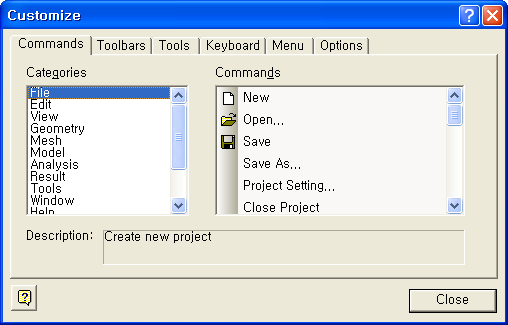
<Commands> Tab of <Customize>
Commands Tab
In the Command Tab of the Customize Toolbar dialog box, the user can add desired menu by dragging the menu into a Toolbar. To remove a menu, simply drag it out. The customized Toolbar can be initialized by the Reset All button in the Toolbar Tab.
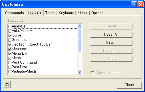
<Toolbars> Tab of <Customize>
Toolbars Tab
Each toolbar can be shown or hidden by checking the items in the tab. By clicking the <New> button, a new toolbar can be created. The customized Toolbar can be initialized by the <Reset All> button.
Keyboard Tab
The user can define shortcut keys for individual functions in the Keyboard Tab. Select a function to create a shortcut in the <Commands> list on the left, and enter the new shortcut key in <Press New Shortcut>. The shortcut keys can be initialized by the <Reset All> button in the Toolbar Tab.
File
|
|
File > New |
|
|
File > Open |
|
|
File > Save |
|
|
File > Print |
|
|
 New
New Open
Open Save
Save Print
Print About
AboutUndo

|
|
|
|
|

 Undo
Undo
 Redo
RedoSelect

|
|
|
|
|
|
|
|
|
|
|
|
|
|
|
|
|
|
|
|
|
|
|
|
|
|
|
|
|
|
|
|
|
 Select
 Unselect
 Unselect All
 Include Intersected
 Select Pick / Window
 Select Circle
 Select Polygon
 Select Polyline
 Query Pick
 Select Displayed
 Select ID
Work plane

|
|
|
|
|
|
|
|
|
|
|
 Display Option
 Toggle Grid
 Grid Setting
 Move Work Plane
Snap

|
|
|
|
|
|
|
|
|
|
|
|
|
|
|
|
|
|
|
|

 Point Snap
 End Snap
 Middle Snap
 Perpendicular
Snap
Perpendicular
Snap Center Snap
 Quadrant Snap
 Intersection
Snap
Intersection
Snap Node Snap
 Off All Snaps
 Snap Lock
View 
|
|
|
|
|
View > Zoom > All |
|
|
View > Zoom > Window |
|
|
- |
|
|
|
|
|
Window > Navigation Window |
|
|
View > View Point > Isometric |
|
|
View > View Point > Front |
|
|
View > View Point > Rear |
|
|
View > View Point > Top |
|
|
View > View Point > Bottom |
|
|
View > View Point > Left |
|
|
View > View Point > Right |
|
|
View > View Point > Normal |
|
|
View > View Point > Previous |
|
|
- |
|
|
- |
|
|
- |
|
|
- |
|
|
- |
|
|
View > Dynamic View > Zoom |
|
|
View > Dynamic View > Pan |
|
|
View > Dynamic View > Rotate |
|
|
- |
|
|
- |
|
|
- |
|
|
- |
|
|
- |
 Reset
Reset Zoom All
 Zoom Window
 Zoom Grid
 Observer Window
 Navigation
Window
Navigation
Window Iso View
 Front View
 Rear View
 Top View
 Bottom View
 Left View
 Right View
 Normal View
 Previous View
 Rotation Center
 Rotate Left
 Rotate Right
 Rotate Up
 Rotate Down)
 Dynamic Zoom (Ctrl+LB))
 Dynamic Pan (Ctrl+MB))
 Dynamic Rotate
(Ctrl+RB)
Dynamic Rotate
(Ctrl+RB) Flying View
 Toggle Bounding
Box
Toggle Bounding
Box Toggle Face Iso-Lines
 Perspective View
 Rendering Option
Measure

|
|
|
|
|
|
|
|
- |
 Distance/Angle
 Geometric Property
 Toggle Tool Tip
Curve

|
|
|
|
|
|
|
|
|
|
|
|
|
|
|
|
|
|
|
|
|
|
|
|
|
|
|
|
|
|
|
|
|
|
|
|
|
|
|
|
|
|
|
|
|
|
|
|
|
|
|
|
|
|
|
|
|
|
|
|
|
|
|
|
|
|
|
|
|
|
|
|
|
|
|
|
|
|
|
|
|
|
|
|
|
|
|
|
|
|
|
|
|
|
|
|
|
|
|
|
|
|
|
|
|
|
|
|
|
|
|
|
|
|
|
|
|
|
|
|
|
|
|
|
|
- |
 Point
Point Line 2D
 Polyline 2D
 Rectangle 2D
 Arc 2D
 Circle 2D
 Ellipse 2D
 B-Spline 2D
 Hyperbola 2D
 Parabola 2D
 Polygon 2D
 Profile 2D
 Tunnel 2D
 Line 3D
 Polyline 3D
 Arc 3D
 B-Spline 3D
 Helix 3D
 Edge on Face
 Shortest Path Line
 Surface Intersection Curve
 Offset Curve
 Extrude Point
 Tangent from Curve
 Tangent Line to Conic Curve
 Fillet Edge
 Chamfer Edge
 Extend 2D Edge
 Extend 3D Edge
 Trim Edge
 Intersect Edge
 Break Edge
 Merge Edge
 Make Wire
 Coincide Line-Ends
 Check Duplicate
 Simplify B-Spline
 Translate Shape
 Rotate Shape
 Mirror Shape
 Delete
 Previous Command
Surface

|
|
|
|
|
|
|
|
|
|
|
|
|
|
|
|
|
|
|
|
|
|
|
|
|
|
|
|
|
|
|
|
|
|
|
|
|
|
|
|
|
|
|
|
|
|
|
|
|
|
|
|
|
|
|
|
|
|
|
|
|
|
|
|
|
|
|
|
|
|
|
|
|
|
|
|
|
|
|
|
|
|
|
|
|
|
|
|
|
|
|
|
|
|
|
|
|
|
|
|
|
- |
 Coons Face
 NURBS Face
 Plane Face
 Grid Face
 Point face
 Extrude
 Revolve
 Loft
Loft Sweep
Sweep Fillet Shape
 Chamfer Shape
 Offset shape
 Sew Surface
 Fuse Surface
 Trim 2 Surfaces
 Trim Surface
by Curve
Trim Surface
by Curve Divide Surface
by Curve
Divide Surface
by Curve Divide Surface
by Surface
Divide Surface
by Surface Imprint on Surface
 Remove Sub-Face
 Extract Sub-Shape
 Explode Shape
 Shape Color
 Check Shape
 Check Duplicates
 Merge Face-Edge
 Break Face-Edge
 Simplify B-Spline
 Repair Factory
 Translate Shape
 Rotate Shape
 Mirror Shape
 Delete
 Previous Command
Solid

|
|
|
|
|
|
|
|
|
|
|
|
|
|
|
|
|
|
|
|
|
|
|
|
|
|
|
|
|
|
|
|
|
|
|
|
|
|
|
|
|
|
|
|
|
|
|
|
|
|
|
|
|
|
|
|
|
|
|
|
|
|
|
|
|
|
|
|
|
|
|
|
|
|
|
|
|
|
|
|
|
|
|
|
|
|
|
|
|
|
|
|
|
|
|
|
|
|
|
|
|
|
|
|
|
|
|
|
|
|
|
|
|
- |
 Cylinder
 Cone
Cone Box
Box Wedge
Wedge Sphere
 Torus
Torus Extrude
 Revolve
 Loft
Loft Sweep
Sweep Fillet Shape
 Chamfer Shape
 Offset Shape
 Draft Face
 Shell Solid
 Local Prism
 Fuse
Fuse Cut
Cut Common
 Trim Solid
 Divide Solid
by Surface
Divide Solid
by Surface  Embed Solid
 Shell to Solid
 Compound Shape
 Explode Shape
 Shape Color
 Check Shape
 Check Duplicates
 Merge Face-Edge
 Break Face-Edge
 Optimize Tolerance
 Simplify B-Spline
 Repair Factory
 Translate Shape
 Rotate Shape
 Mirror Shape
 Delete
 Previous Command
Geometry

|
|
|
|
|
|
|
|
|
|
|
|
|
|
|
|
|
|
|
|
|
|
|
|
|
|
|
|
|
|
|
|
|
|
|
|
|
|
|
|
|
|
|
|
|
|
|
|
|
|
|
|
|
|
|
|
|
|
|
|
|
|
|
|
|
|
|
|
- |
 Translate Shape
 Rotate Shape
 Mirror Shape
 Scale Shape
 Project Shape
 Attach Shape
 Remove Face/Edge
 Remove Sub-Face
 Remove Hole
 Remove Imprinted
Object
Remove Imprinted
Object Extract Sub-Shape
 Compound Shape
 Explode
 Shape Color
 Check Shape
 Check Duplicates
 Merge Face-Edge
 Break Face-Edge
 Optimize Tolerance
 Simplify B-Spline
 Repair Factory
 Delete
 Previous Command
Auto/Map-Mesh

|
|
|
|
|
|
|
|
|
|
|
|
|
|
|
|
|
|
|
|
|
|
|
|
|
|
|
|
|
|
|
|
|
|
|
|
|
|
|
|
|
|
|
|
|
|
|
|
|
|
|
|
|
|
|
|
|
|
|
|
|
|
|
|
|
|
|
|
|
|
|
|
|
|
|
|
|
|
|
|
|
|
|
|
|
|
|
|
|
|
|
|
|
|
|
|
|
|
|
|
|
|
|
|
|
|
|
|
|
|
|
|
|
|
|
|
- |
|
|
- |
 Mesh Preference
 Solid Mesh Control
 Face Mesh Control
 Edge Mesh Control
 Global Mesh Size
 Shape Mesh Size
 Face Mesh Size
 Edge Mesh Size
 Point Mesh Size
 Edge Custom Size
 Match Edge Seeds
 Display Mesh
Seed
Display Mesh
Seed Delete Mesh Control
 Auto-Mesh Edge
 Auto-Mesh Face
 Auto-Mesh Solid
 Auto-Mesh Planar
Area
Auto-Mesh Planar
Area Auto-Mesh 4-Edge
Area
Auto-Mesh 4-Edge
Area Auto-Mesh 2D
to 3D
Auto-Mesh 2D
to 3D Map-Mesh Face
 Map-Mesh Solid
 Map-Mesh 3-Edge
Area
Map-Mesh 3-Edge
Area Map-Mesh k-Edge
Volume
Map-Mesh k-Edge
Volume Map-Mesh 3-Edge
Area
Map-Mesh 3-Edge
Area Map-Mesh 4-Node
Area
Map-Mesh 4-Node
Area  Remesh Edge
 Remesh Face
 Check Mesh
 Mesh Quality
 Translate Mesh
 Rotate Mesh
 Mirror Mesh
 Scale Mesh
 Show Elem/Node
 Hide Elem/Node
 Inverse Visibility
 Show All
 Show previous
 Show/Hide Dialog
 Previous Command
Protrude-Mesh

|
|
|
|
|
|
|
|
|
|
|
|
|
|
|
|
|
|
|
|
|
|
|
|
|
|
|
|
|
|
|
|
|
|
|
|
|
|
|
|
|
|
|
|
|
|
|
|
|
|
|
|
|
|
|
|
|
|
|
|
|
|
|
|
|
|
|
|
|
|
|
|
|
|
|
|
|
|
|
|
|
|
|
|
|
|
|
|
|
|
|
|
|
|
|
|
|
|
|
|
|
|
|
|
|
|
|
|
 Global Mesh Size
 Edge Mesh Size
 Match Edge Seeds
 Display Mesh
Seed
Display Mesh
Seed Delete Mesh Control
 Auto-Mesh Edge
 Auto-Mesh Face
 Auto-Mesh Planar
Area
Auto-Mesh Planar
Area Map-Mesh Face
 Map-Mesh 3-Edge
Area
Map-Mesh 3-Edge
Area Map-Mesh 4-Node
Area
Map-Mesh 4-Node
Area Extrude Mesh
 Revolve Mesh
 Sweep Mesh
 Project Mesh
 Offset Mesh
 Fill Mesh
 Merge Node
 Project Node
 Create Element
 Extract Element
 Change Element
Parameter
Change Element
Parameter Delete Element
 Check Mesh
 Mesh Quality
 Translate Mesh
 Rotate Mesh
 Mirror Mesh
 Scale Mesh
 Show Elem/Node
 Hide Elem/Node
 Inverse Visibility
 Show All
 Show Previous
 Show/Hide Dialog
 Previous Command
Mesh 
|
|
|
|
|
|
|
|
|
|
|
|
|
|
|
|
|
|
|
|
|
|
|
|
|
|
|
|
|
|
|
|
|
|
|
|
|
|
|
|
|
|
|
|
|
|
|
|
|
|
|
|
|
|
|
|
|
|
|
|
|
|
|
|
|
|
|
|
|
|
|
|
|
|
|
|
|
|
|
|
|
|
|
|
|
|
|
|
|
|
|
|
|
|
|
|
|
|
|
|
|
|
|
|
|
|
|
|
|
|
|
|
|
- |
|
|
- |
|
|
- |
|
|
|
|
|
|
|
|
|
|
|
|
|
|
|
|
|
- |
|
|
- |
 Create Node
 Project Node
 Merge Node
 Align Node
 Delete Node
 Query Node
 Node Table
 Create Element
 Create Point
Spring
Create Point
Spring Create Link
 Create Surface
Spring
Create Surface
Spring Create Interface
 Create Pile Element
 Connection
 Extract Element
 Change Element
Parameter
Change Element
Parameter Divide 1D Element
 Divide 2D Element
 Divide 3D Element
 Modify Element
Topology
Modify Element
Topology Smooth Element
 Delete Element
 Measure Element
 Query Element
 Element Table
 Check Mesh
 Mesh Quality
 Translate Mesh
 Rotate Mesh
 Mirror Mesh
 Scale Mesh
 Sweep-Translate
 Create Mesh
Set
Create Mesh
Set Copy Mesh Set
 Rename Mesh Set
 Mesh Set Operation
 Renumber
  Element Csys
 Node ID
 Element ID
 Show Elem/Node
 Hide Elem/Node
 Inverse Visibility
 Show All
 Show Previous
 Show/Hide Dialog
 Previous Command
Analysis

|
|
|
|
|
|
|
|
|
|
|
|
|
|
|
|
|
|
|
|
|
|
|
|
|
|
|
|
|
|
|
|
|
|
|
|
|
|
|
|
|
|
|
|
|
|
|
|
|
|
|
|
|
|
|
|
|
|
|
|
|
|
|
|
|
|
|
|
|
|
|
|
|
|
|
|
|
|
|
|
|
|
|
|
|
|
|
|
|
|
|
|
|
|
|
|
|
|
|
|
|
|
|
|
|
|
|
|
|
|
|
|
|
- |
|
|
- |
|
|
- |
 Coordinate Systems
 Function
 Generalized Space
Function
Generalized Space
Function Truss Nonlinear
Elastic Function
Truss Nonlinear
Elastic Function Attribute
 Material
 Property
 Unsaturated Property
Function
Unsaturated Property
Function Load Set
 Change Load Set
 Self Weight
 Force
Force Moment
 Pressure Load
 Prescribed Displacement
 Line Beam Load
 Element Beam
Load
Element Beam
Load Nodal Temperature
 Element Temperature
 Temperature Gradient
 Prestress
 Nodal Mass
 Boundary Set
 Change Boundary
Set
Change Boundary
Set Supports
 Ground Supports
 Nodal Head
 Nodal Flux
 Seepage Face
 Surface Flux
 Seepage Boundary
Function
Seepage Boundary
Function Circular Surface
 Polygonal Surface
 Change Element
Attribute
Change Element
Attribute General Analysis
Control
General Analysis
Control Analysis Case
 Solve
Solve Pre-mode
 Post-mode
 Previous Command
Post Data

|
| |
|
| |
|
| |
|
| |
|
| |
|
| |
|
| |
|
| |
|
| |
|
|
|
|
|
|


 Pre-mode
 Post-mode
|
|
|
|
| |
|
| |
|
| |
|
| |
|
| |
|
| |
|
| |
|
| |
|
| |
|
|
|
|
|
|
 Visualization


 Pre-mode
 Post-mode